Description
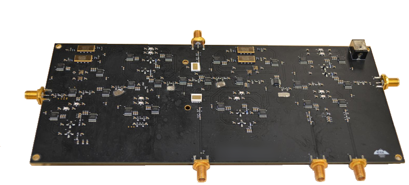
[vc_row][vc_column][vc_column_text]Rover RCRF is CEI’s latest reconfigurable RF board with design, simulation, and synthesis software using NI AWRs VSS and Microwave Office. Quickly create an up converter, down converter, Heterodyne amplifier, or a variety of RF systems using this reconfigurable RF system demonstrator. In minutes, you can design a circuit, simulate it, realize it in hardware, and see how it performs on your lab bench. Then quickly redesign it however you’d like: try a different filter, add an amplifier block or notch out a spur, and see instant results. Choose the Rover-RCRF for your next RF design!
Not quite what you need? Need a custom version? CEI can tailor an RCRF solution for you in 2 to 4 weeks. Academic bundles available with NI AWR Microwave Office included. Contact us to learn more.[/vc_column_text][vc_column_text][/vc_column_text][/vc_column][/vc_row][vc_row][vc_column width=”1/2″][vc_column_text]
Applications
- Wireless communications systems
- Test and measurement
- Automated Test Equipment (ATE)
- Proprietary wired/wireless communication systems
- Frequency planning
- Radar systems
- EW, ECM, ESM and other RF and microwave systems
Benefits
- Reconfigurable RF system demonstrator lets you specify your RF circuit, simulate it, then instantly configure it in hardware.
- Connect to a signal generator and spectrum analyzer, then change your design and see the RF effects in real time.
- Design is simple — drag desired components from the component library and drop them onto the screen.
- Design Check software (included) lets you know whether the device can create the system you’ve drawn.
- Design, simulate, synthesize and configure the device without ever leaving AWR’s VSS window.
- Save your designs to share or work with later.
- Hardware device can be programmed and reprogrammed as often as you like.
- Device configuration is non-volatile even when removed from the design workstation. The device maintains your design when powered back on.
- Design-to-device fidelity is ensured by internal modeling, error detection and positive acknowledgement architecture.
[/vc_column_text][/vc_column][vc_column width=”1/2″][vc_column_text]
Highlights
- Design, simulate and test in minutes in NI AWR’s VSS window.
- Test unlimited designs with no board re-spins.
- Almost 20,000 configurations.
- Drag and drop user interface using NI AWR’s VSS window.
- Ideal for: RF labs, test and measurements, and university RF courses.
- “How To” CD included.
- Development of component specifications.
- Algorithm development.
- Creation of modulated signals.
- Co-simulation with circuit tools.
- End-to-end simulations.
- Predicting wireless conformance tests.
- Hardware-in-the-loop simulations.
Additional Features
- Hardware module implements 39 selectable RF components in five stages, including one pass-through for each stage.
- Stage 5 contains a band reject filter with software tunable center frequency.
- Six SMA connections.
- RF input and output
- Connections out to an external circuit and back in.
- LO input to sum mixer.
- LO input to diff mixer.
- Uses AWR’s VSS software for data input and simulation.
- Includes component library, all DRC and synthesis software, and controller module.
- Non-volatile memory restores the last configuration on power-up or reset.
- Includes users guide and 6′ USB cable to connect the designer’s PC to the RF-FPGA.
- Most on-board components operate around 70 MHz, 811.5 MHz, or 1960 MHz.
[/vc_column_text][/vc_column][/vc_row][vc_row][vc_column][/vc_column][/vc_row][vc_row][vc_column][vc_column_text]
